ATmegaTQ3201 - ATmega microcontrolller in TQFP32 packages
Overview
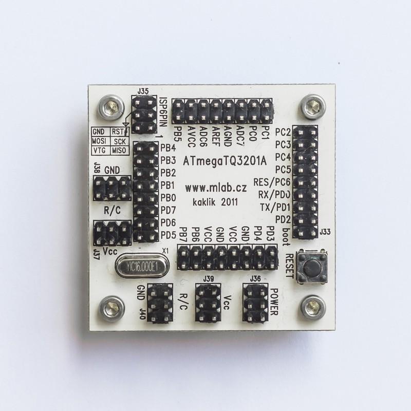
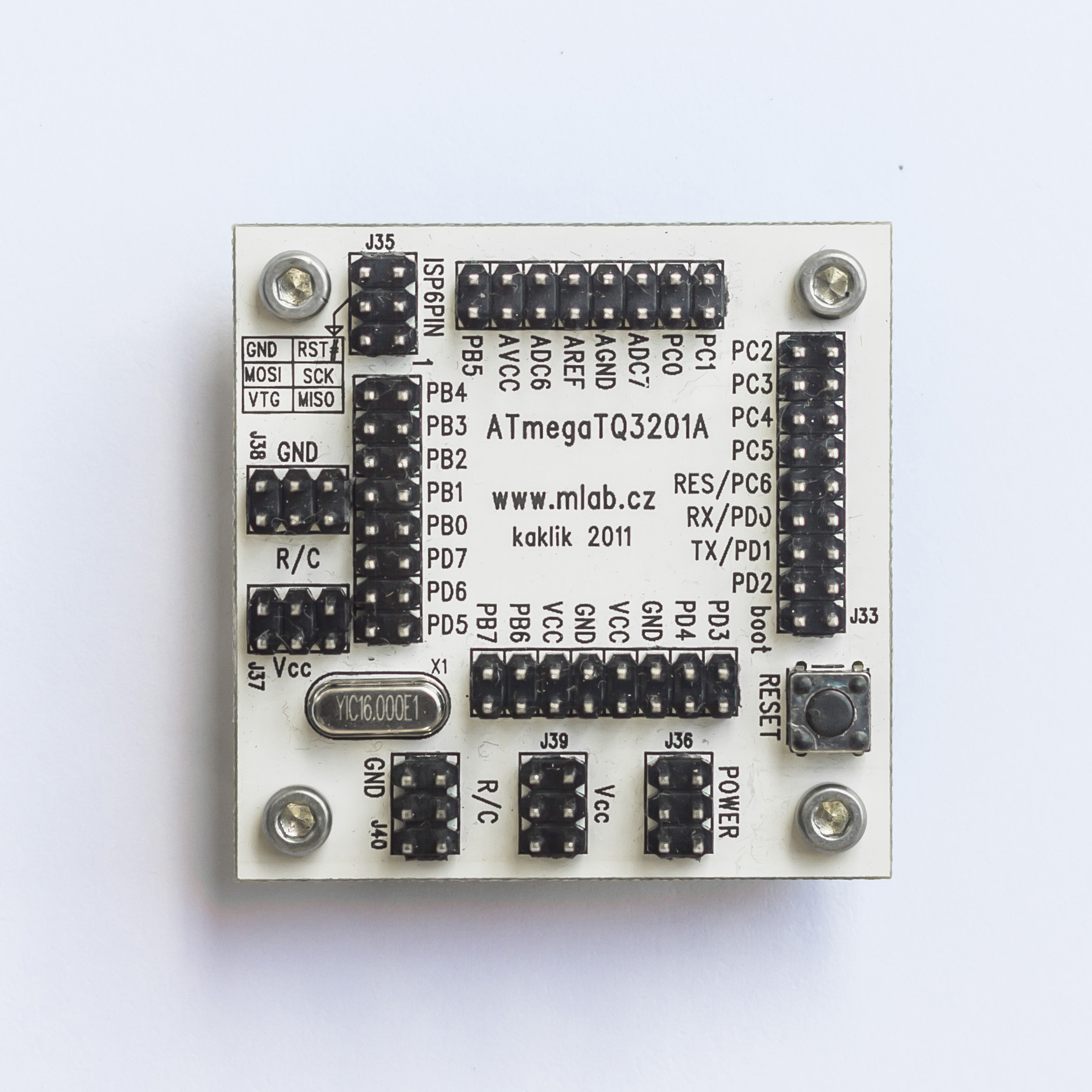
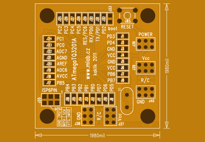
The ATmegaTQ3201 is a processor module designed for working with ATMEL processors in TQFP32 packages. This module includes a processor and is equipped with a RESET button and an ATMEL ISP 6 PIN programming connector. The module supports the use of a standard crystal or external clock.


Technical Specifications
- Power Supply: 1.8V to 5.5V (depending on the processor used)
- Processor: ATmega8 / ATmega8L (or any other TQFP32 package)
- Current Consumption: 12mA at 8MHz with crystal
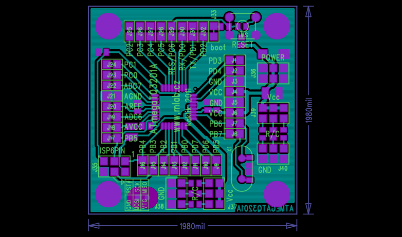
- Dimensions: 51x51x15mm (height above the carrier board)
Features
- Power Supply: The module is powered via connector J33. Diode D1 protects against reverse polarity.
- Clock Source Options:
- Internal RC oscillator (default setting, 1MHz)
- External crystal oscillator with crystal X1
- External RC oscillator (R3/C5)
- External clock signal source on pin XTAL1
- ISP Connector: Standard 6-pin ISP connector for programming.
- Reset Button: Equipped with a RESET push button for easy reset functionality.
Mechanical Construction
The module is a standard MLAB module with mounting corner posts for secure installation.
Assembly and Initialization
Assembly
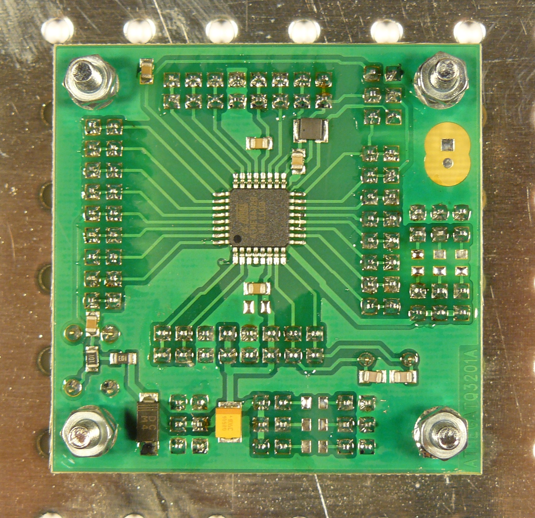
- Use minimal solder for the processor. Pre-tin the pads if necessary and secure the processor by soldering two opposite legs first.
- Crystal can be soldered directly or mounted in precision sockets for easy replacement.
- In a pinch, the SMD inductor can be replaced with a jumper or a standard inductor, but this will affect the A/D converter noise performance.
Components
- Resistors: R1 (100Ω), R2, R101, R102, R103 (10kΩ), R3 (not populated)
- Capacitors:
- Ceramic: C4, C5 (22pF), C101, C102, C103 (10nF), C104 (470nF), C105 (4.7µF), C2, C3, C6, C7 (100nF)
- Electrolytic: C1 (10µF/6.3V)
- Inductors: L1 (10µH)
- Diodes: D1 (M4)
- Integrated Circuits: U1 (ATmega8L-8AU)
- Crystals: X1 (specify frequency as needed)
- Mechanical Parts: Various jumpers, connectors, and screws as listed in the detailed documentation.
Example Program
Here is a basic program to blink an LED using the ATmegaTQ3201A module:
#define F_CPU 1000000UL  // 1MHz internal RC oscillator

#include <avr/io.h>
#include <util/delay.h>

// Delay function
void xDelay_ms(unsigned int Time) {
    for(; Time != 0; Time--) {
        _delay_ms(1);  // Library function with limited maximum delay
    }
}

int main() {
    DDRC |= 1;   // Set port PC0 as output
    for(;;) {    // Infinite loop
        PORTC |= 1;  // Set PC0 high
        xDelay_ms(500);  // Wait for 1/2 second
        PORTC &= ~1;  // Set PC0 low
        xDelay_ms(500);  // Wait for 1/2 second
    }
    return 0;
}
To program the chip with the above example, use the following command:
avrdude -p m8 -c picoweb -P lpt1 -U flash:w:BLIK_ATmega8.hex:a -E noreset
Additional Information
For more details and updates, visit the MLAB website and the MLAB wiki.